Abstract
Along the western flank of the northern margin (Central Pontides) of the Central Anatolian Plateau, the humidity from the Black Sea is much higher than the central and eastern flanks and creates a complex relationship between surface and tectonic processes by triggering intense mass wasting activity and aggradation within narrow valleys. We identified three incised fill terrace levels and used Optically Stimulated Luminescence (OSL) dating to calculate fluvial sediment ages and cosmogenic ³⁶Cl exposure dating to calculate limestone boulders exposure ages across the terrace surface.
Stratigraphical interpretations and OSL ages of the lowest levels revealed that a fluvial fill terrace formed in the main valley at 275.6 ± 12.8 ka and was overlain by a main river-tributary junction alluvial fan that was abandoned at 39.5 ± 3.5 ka. The results collectively show the influence of climate, topography, hillslope processes, and lithology on aggradation-incision patterns of main rivers. Prolonged aggradation can prevent the channel equilibrium required to calculate rock uplift rates while also causing a new base-level and aggradation upstream. This effect can be exacerbated in uplifting mountainous regions with limited depositional areas.
Bedrock incision rates based on the fluvial terrace age were between 0.15 and 0.2 mm/a since 39.5 ± 3.5 ka. However, the high aggradation within this segment of the main valley prevented incision of the channel bedrock for long periods, causing a potential underestimation of the rock uplift rate calculation. Our local period of aggradation appears to be related to increased aggradation and decreased bedrock incision rates measured 14 km upstream that were previously assumed to be the result of decreased tectonic uplift rates. This demonstrates the importance of corroborating strath terrace incision rate estimations with ages and incision rates of downstream fill terraces, if present, to check for potential interference with the tectonic signal.
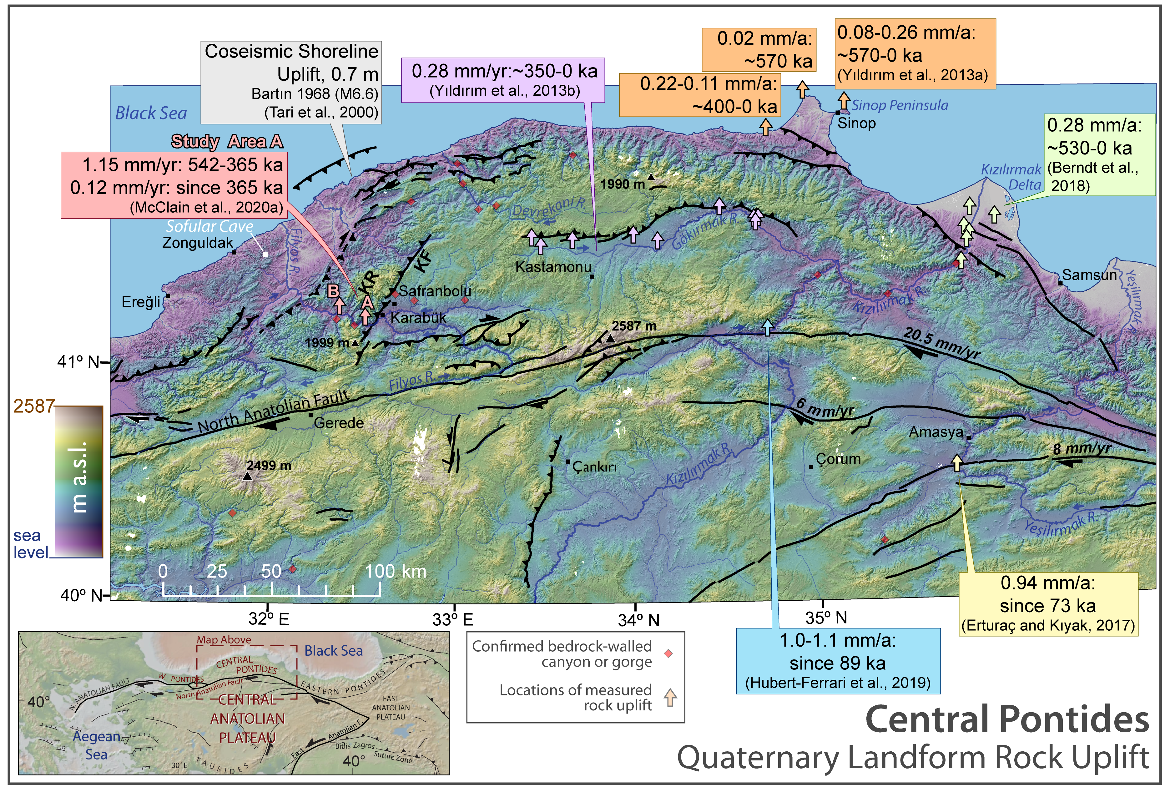
Figure 1
Topographic map of the Central Pontides at the northern margin of the Central Anatolian Plateau. The study area is located on the hanging wall of the Karabük (reverse) Fault, which is under transpression from the ~250 km-long restraining bend of the North Anatolian Fault. The main river of the study (Filyos River) flows along the North Anatolian Fault before turning west and northwest, where it bisects the Karabük Range en route to the Black Sea. Previous rock uplift rates studies of the transpressional Central Pontides are depicted in captions, with sample locations at arrows. Red diamonds mark locations of major bedrock-walled canyons or gorges. However, these are not comprehensive due to the possibility of minor canyons in less accessible tributaries. Faults are illustrated with slip rates when known. A map of the study area is seen in Fig. 2 (white box). Topography and hillshade were generated from the Advanced Land Observation System (ALOS) 2 Digital Surface Model (2014). KF = Karabük Fault, KR = Karabük Range.
I used my own version of the viridis color ramp. The viridis ramp is a ramp that is readable in colorblind formats and prevents misleading visual interpretations regardless of colorblindness. It is often used to illustrate scientific data. I added a shade of light brown to the ramp for the highest elevations to give a greater effect of the topographic relief.
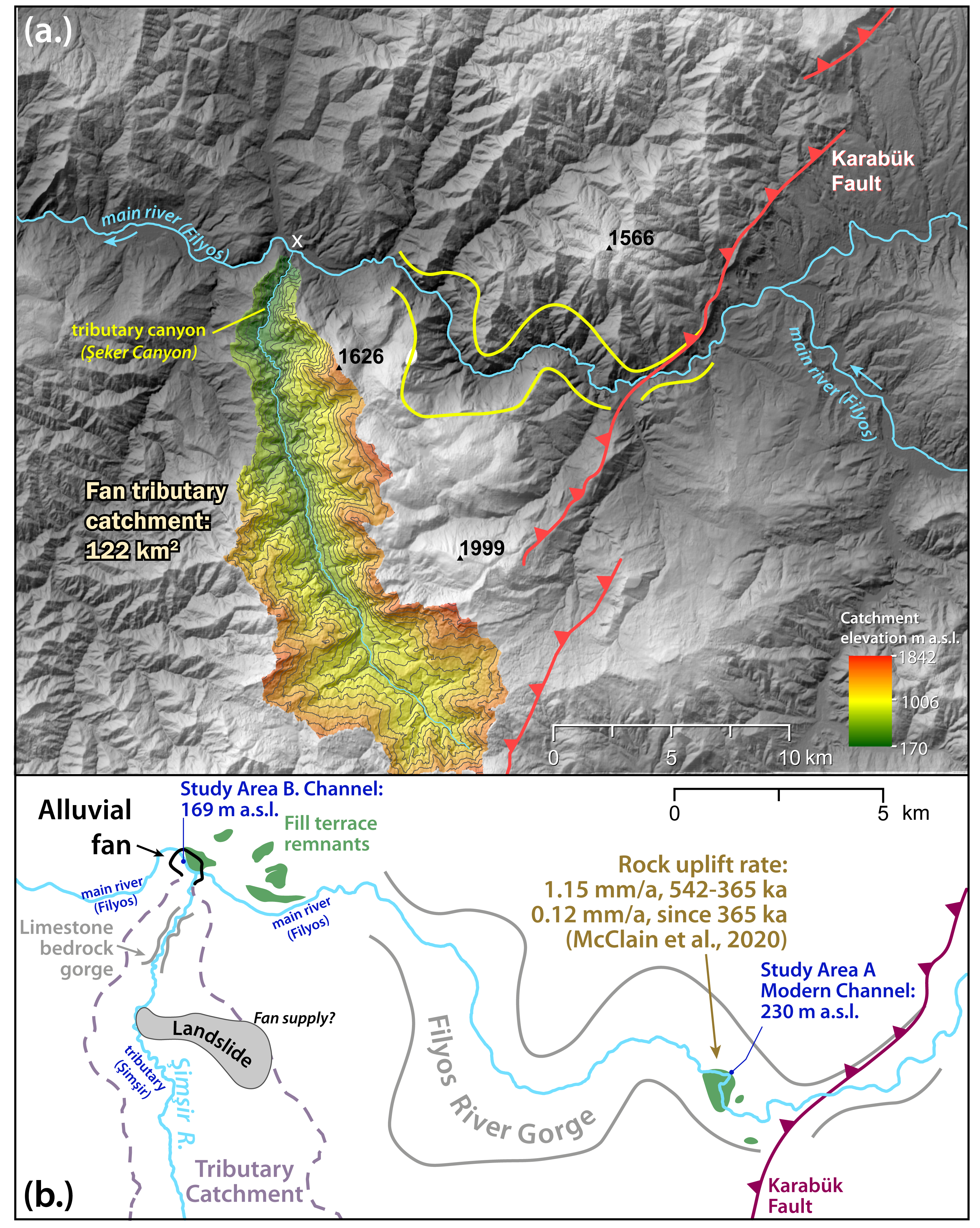
Figure 2
(a.) Topographic hillshade map of the study area, showing the tributary catchment of interest (Şimşir River) in relation to the main river. The contour interval in the tributary catchment is 100 m. The location of the two bedrock gorges are marked in yellow. (b.) Simplified map of the study area without topography. This map shows the arrangement of the study setting, with the Karabük Fault, fluvial terraces of McClain et al. (2020), and the main gorge located upstream to the east of the study area. It also shows the location of the tributary bedrock gorge and landslide of interest to the south, with the approximate fan location at the confluence with the main river. The modern channel elevations of the study area relative to the upstream study area are important when considering base-level changes and aggradation influence upstream.
My goal for this figure was to show the location of the upstream Filyos River Gorge and the catchment of the tributary suspected of supplying an alluvial fan at the junction with the main river valley (Filyos). The lower image was made to simplify the geomorphology of the environment.
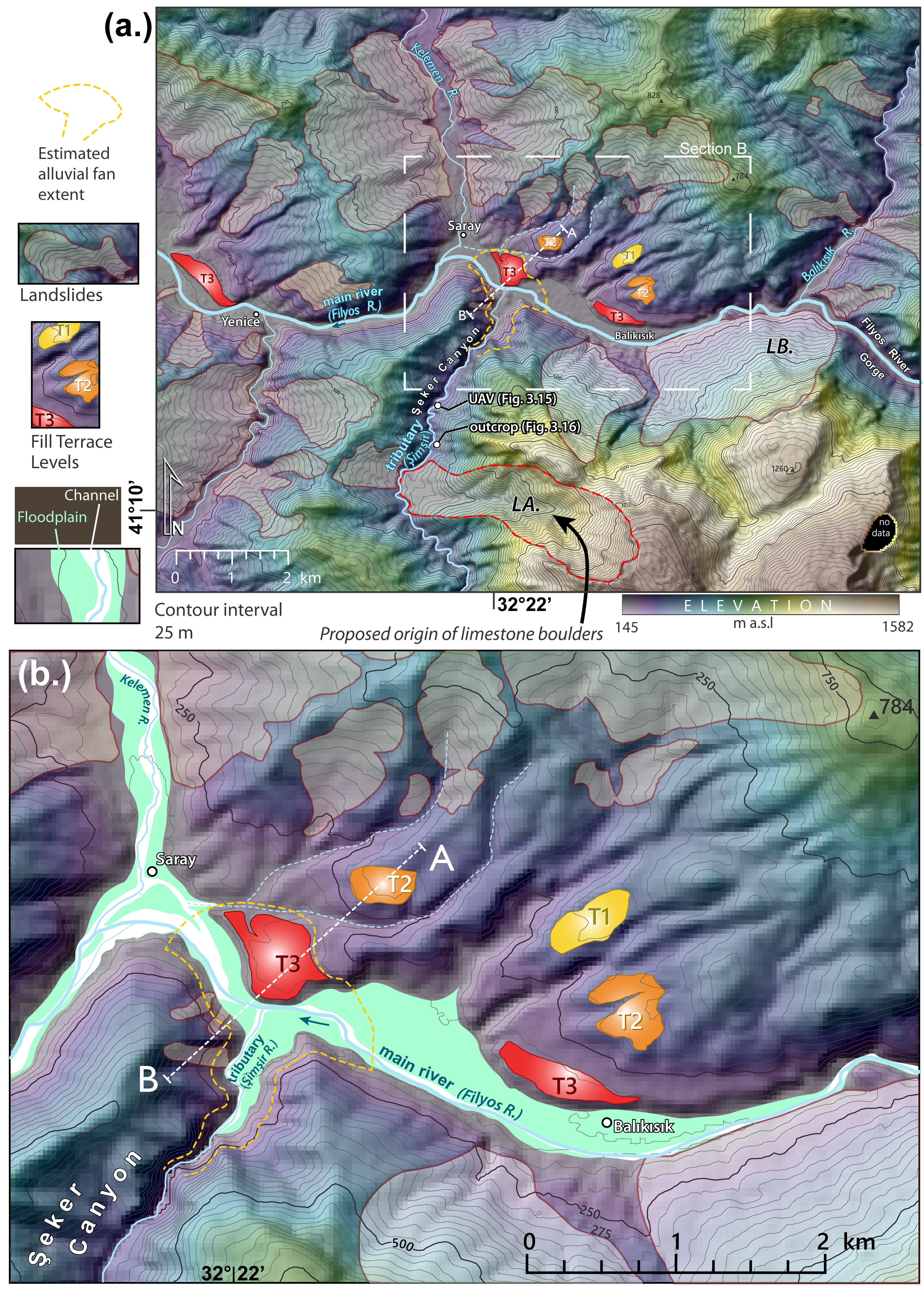
Figure 3
Topographic map downstream from the Filyos River Gorge, showing the locations of fluvial terraces, landslides, possible extent of proposed alluvial fan, and Figs. 9 and 10 photo locations (a.). The main river (Filyos) flows westward and the tributary of interest (Şimşir) flows northward. A closer view of the floodplain area and tributary junction is mapped below (b.). The A-B topographic profile of Fig. 11 is depicted with a white dashed line. Landslides marked LA. and LB. are discussed in this paper as are the dashed intermittent channels adjacent to T2.
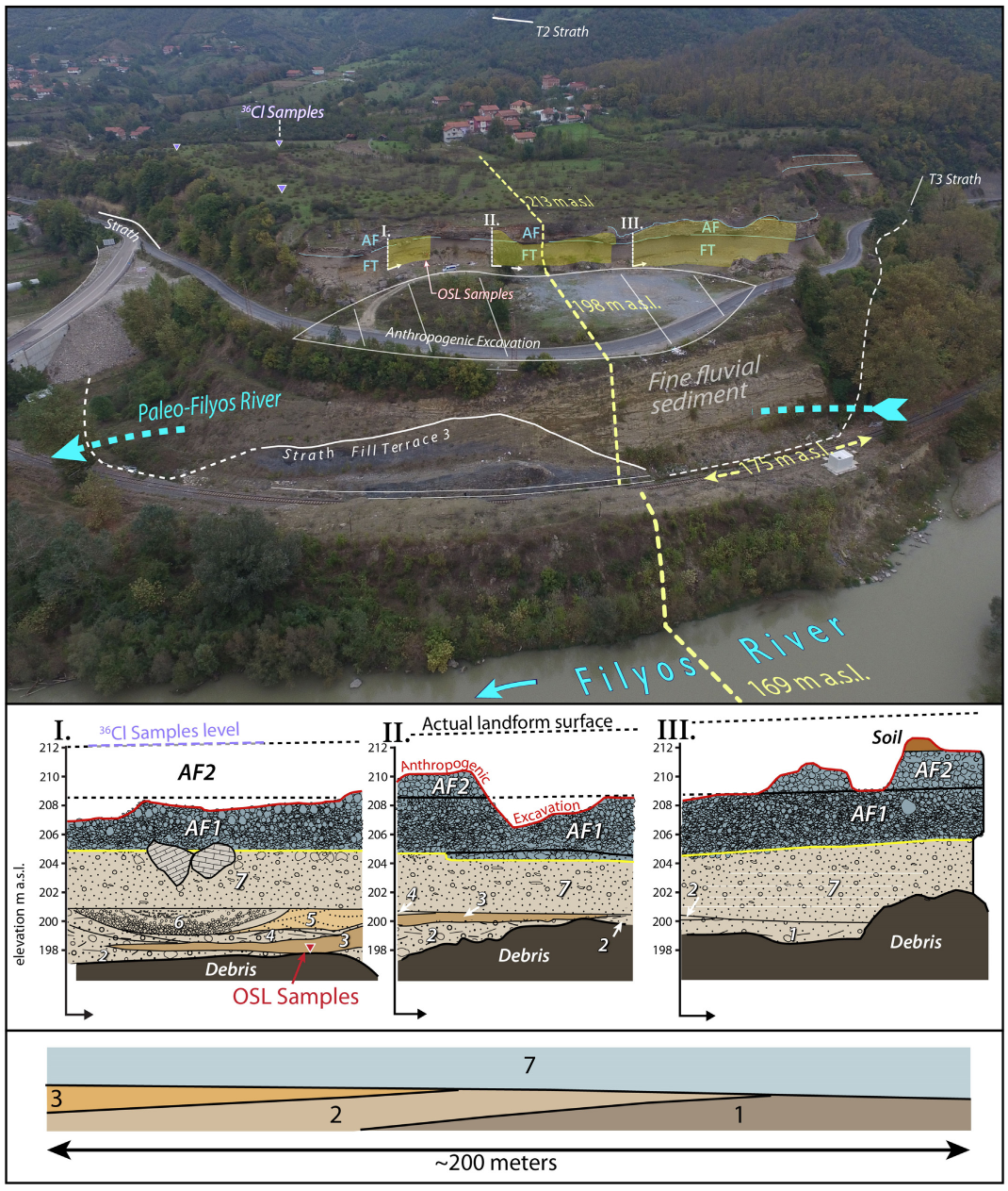
Figure 4
UAV view of the junction terrace, which is part of T3, the lowest terrace level (top). Sample locations are labeled, the bedrock strath is marked in white, and the horizon between fluvial and alluvial fan layers is marked on the outcrop. Y-axes I, II, and III are marked at their locations and represent the axes in the middle illustration. Illustration of exposed alluvial and fluvial sediments in three sections (middle). Simplified illustration of the orientation of layers 1, 2, 3, and 7, which correspond to the progradation of a longitudinal bar (bottom).
Illustrating the stratigraphy like this in Adobe Illustrator took a long time. However, I think it was worth it. It organized the different sediment packages well. None of the sediment or exposure ages would have been meaningful here without analysis of the sediment facies.
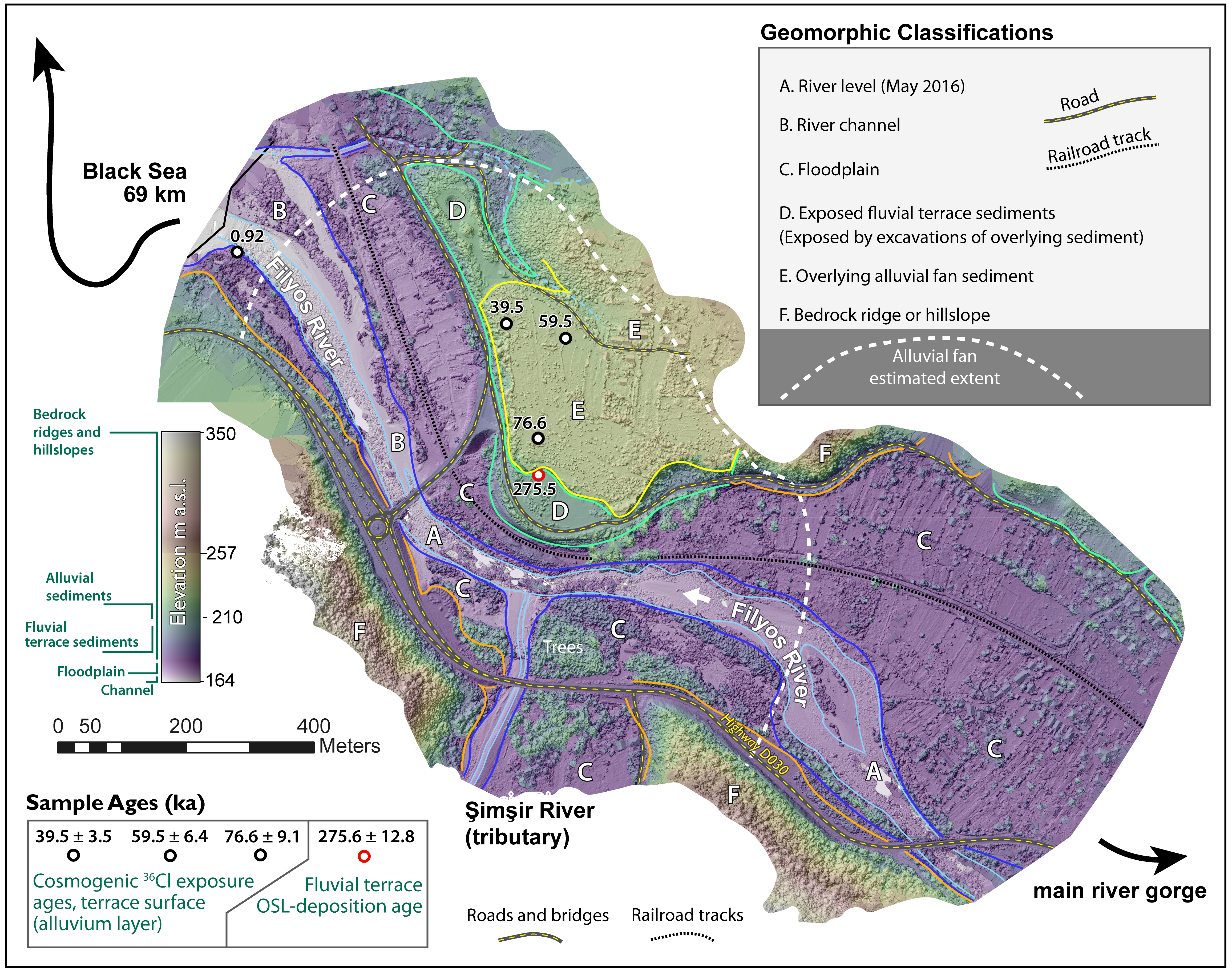
Figure 5
Digital surface model (DSM) produced at the confluence of the Filyos (main) and Şimşir (tributary) rivers, showing the junction terrace (T3) location and the classification of different surface features that were confirmed based on elevation and field observations. A remnant of the valley infill is preserved where labeled 'D.' While most of it eroded where there are now broad floodplains, a 1 km² tributary junction alluvial fan is proposed to have formed downstream (north) of the tributary canyon (Şeker Canyon) and in the main river valley. The layers from this fan are preserved where the letter 'E' is marked. Sample ages of the fluvial terrace and the overlying alluvial fan layer are in the lower left and sample locations are on the map. The channel sample in the western margin of the DSM is the inheritance correction boulder, with an age of 0.92 ± 0.1 ka.
Although this high resolution DSM was useful for the study, it was more icing on the cake for this location. My intention was to fly the UAV further east towards the end of the Filyos River Gorge. I wanted to map all the fluvial fill terrace levels, but these flights were much more energy intensive than we realized and we ran out of battery. Since most of the key features were in the lower 100 meters, I wanted most of the viridis color ramp to amplify differences between floodplain and anything above it. Therefore I compressed the lower half of the color ramp and extended the colors above 257 m to a brown and gray.
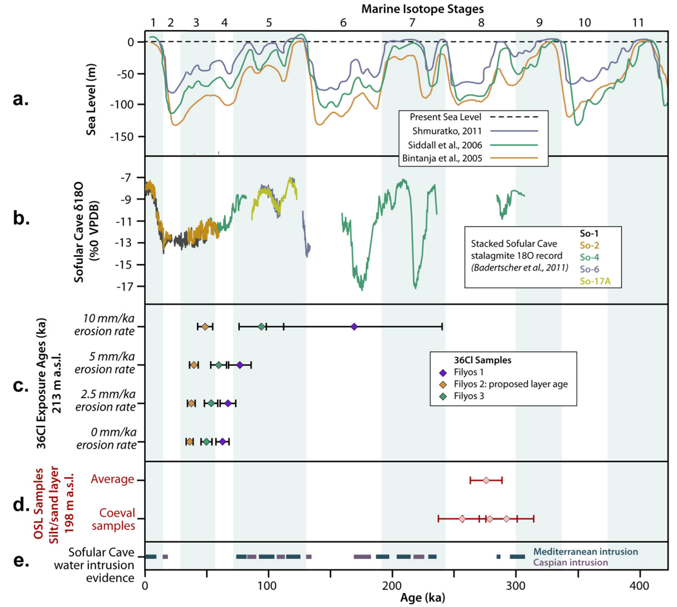
Figure 6
Sea level curves from MIS 11 through present, modified from Yıldırım et al. (2013b) and based on Bintanja et al. (2005), Siddall et al. (2006), and Shmuratko (2001) (A.). Humid interglacial periods are shaded blue and their terminations are based on Lisiecki and Raymo (2005). Simplified Sofular Cave δ¹⁸O stalagmite records, modified from Badertscher et al. (2011) (B.). Cosmogenic ³⁶Cl exposure ages of the limestone boulders on the junction terrace alluvial fan layer (C.). Calculations with various erosion rates are illustrated in Section C. OSL-sample ages and uncertainties of three coeval samples and their average age from the fluvial terrace/T3 sediments (D.). Evidence of water intrusions into the Black Sea from the Mediterranean and Caspian Seas from the nearby Sofular Cave (Badertscher et al., 2011) (E.).
I wanted to demonstrate when deposition would be more likely in this region. I used the color blue for warm periods (interglacials) because warm periods in this area are associated with higher precipitation. During cool periods, the Black Sea (lake) coastline is much farther from its current position, resulting in more arid conditions. It is important to correlate timing of sediment aggradation because cooler periods have less hillslope-stabilizing vegetation cover. Warm periods have more vegetation cover but also more potential for climatic events that could destabilize hillslopes.
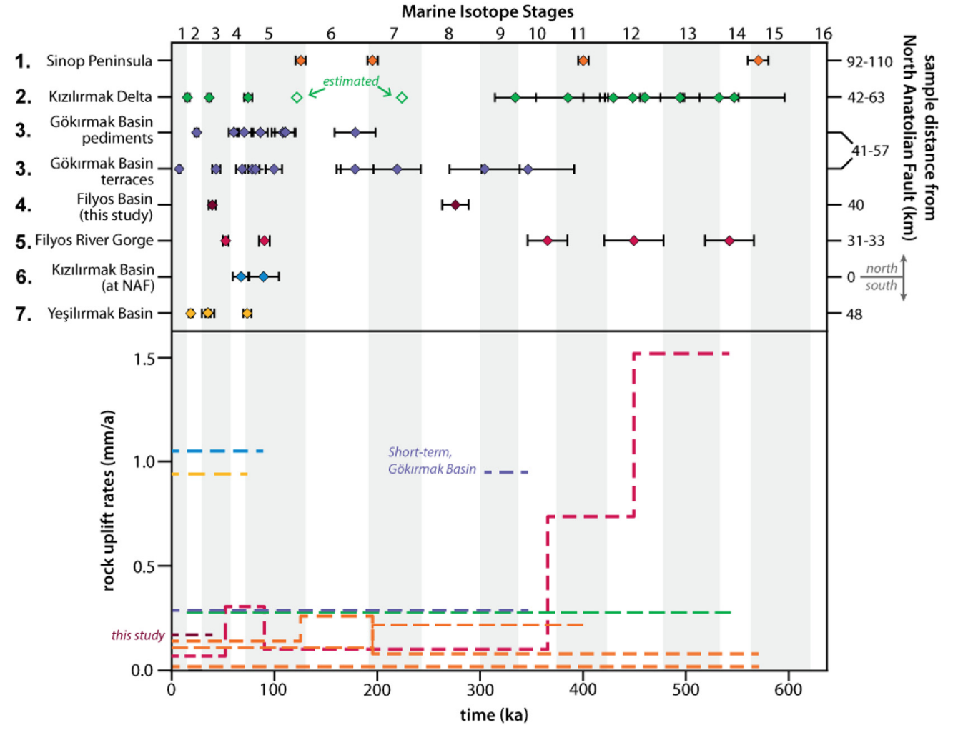
Figure 7
(Top) Landform ages from different rock uplift rate studies throughout the Central Pontides. Each number corresponds to locations in Fig. 1 and are arranged by distance from the North Anatolian Fault with number 6 located at the fault. (1.) Sinop Peninsula marine terrace ages from Yıldırım et al. (2013a). (2.) Kızılırmak Delta strath terrace, fill terrace, and delta terrace ages from Berndt et al. (2018). (3.) Gökırmak Basin strath terrace and pediment surface ages from Yıldırım et al. (2013b). (4.) Filyos River main river fill terrace and tributary junction alluvial fan ages of this study. (5.) Filyos River Gorge strath terrace ages upstream from this study from McClain et al. (2020). (6.) Kızılırmak River Valley fill terrace ages at the North Anatolian Fault in Hubert-Ferrari et al. (2019). Yeşilırmak Valley fluvial terrace ages south of the North Anatolian Fault from Erturaç and Kıyak (2017). (Bottom) Rock uplift rates through time at each study area. Colors correspond to the top section and the map in Fig. 1. The Gökırmak Basin has a long-term uplift rate reported as 0.28 mm/a and illustrated in the chart (Yıldırım et al., 2013b). However, a higher short-term uplift rate is seen in MIS 9 and is comparable in magnitude to other studies. It is also illustrated in the chart. The Sinop Peninsula reported rock uplift rates at three locations and therefore has three orange lines representing rock uplift rates in this chart (Yıldırım et al., 2013a). MIS stage boundaries are based on Lisiecki and Raymo (2005).
The purpose of this figure was to show the timing of terrace formations across the Central Pontides (top) and the calculated rock uplift rates from across the Central Pontides (bottom).